
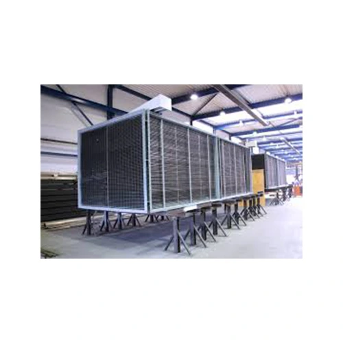
1. What Is a Flue Gas Air Preheater?
A flue gas air preheater (APH) is a heat recovery device used to improve boiler and furnace efficiency by utilizing waste heat from exhaust gases. It transfers heat from hot exhaust gases to the incoming combustion air before it enters the boiler or furnace. This preheated supply helps achieve better fuel combustion, reduces fuel consumption, and increases overall energy efficiency in industrial heating systems and power plants.
2. How Does a Flue Gas Air Preheater Work?
A flue gas air preheater transfers heat from hot exhaust gases to cold combustion air through separate passages. The two process streams do not mix. Instead, heat moves from the hot flue gas to the cooler combustion air. This raises the air temperature before it enters the furnace, helping improve efficiency and reduce fuel use.
Working Principle of a Flue Gas Air Preheater
- Hot Flue Gas Flow: During combustion, hot exhaust gases leave the boiler or furnace and flow through the flue gas air preheater. These gases contain valuable waste heat that can be reused to improve system efficiency.
- Cold Combustion Air Intake: A forced-draft fan draws fresh combustion air into the unit. The cooler air flows through separate passages designed for efficient heat transfer.
- Heat Exchange Process: The hot exhaust gas and cooler combustion air flow through separate channels, tubes, or heat-transfer surfaces. They do not mix. Heat passes through the metal surfaces and preheats the combustion air before it enters the furnace.
- Improved Combustion Efficiency: The preheated combustion air then flows to the burner or furnace. It helps the fuel ignite faster and burn more completely. This improves boiler performance and reduces the amount of fuel needed.
Where Is the Air Preheater Located in a Boiler?
The unit is normally installed after the economizer and before the ESP or baghouse in the exhaust-gas path. On the intake side, it is located after the FD fan or PA fan and before the burner, pulverizer, or furnace.
- Combustion-air path: Ambient air → FD fan or PA fan → air preheater → burner or pulverizer → furnace
- Exhaust path: Furnace → economizer → air preheater → ESP or baghouse → ID fan → chimney or stack
The economizer first recovers heat from the exhaust stream to warm boiler feedwater. The unit then uses the remaining heat to warm incoming combustion air. After heat recovery, the exhaust stream passes through the ESP or baghouse for dust removal, moves through the ID fan, and exits through the chimney or stack.
3. Types of Flue Gas Air Preheaters
Flue gas air preheaters are mainly classified as recuperative or regenerative systems according to how heat is transferred from exhaust gas to combustion air.
1. Recuperative Air Preheaters
A recuperative air preheater transfers heat continuously through a fixed metal surface while keeping the exhaust and combustion-air streams separate. It works as a stationary heat exchanger and does not use a rotating heat-storage element.
Tubular Air Preheater
A tubular design uses metal tubes to transfer heat between hot exhaust and incoming combustion air. Exhaust gas usually flows through the tubes while the combustion air passes around them. This design is durable, simple to maintain, and suitable for boilers, refineries, and process furnaces.
Plate-Type Air Preheater
A plate-type configuration uses thin metal plates to separate the combustion air from the hot exhaust gas. Its compact construction and large heat-transfer area make it suitable for industrial applications where installation space is limited.
2. Regenerative Air Preheaters
A regenerative design uses heat-storage elements to absorb energy from the hot exhaust gas and release it to the incoming combustion air. This design is commonly used in large boilers and thermal power plants.
Rotary Regenerative Air Preheater
A rotary regenerative unit, also called a RAPH, contains a slowly rotating rotor filled with heat-transfer elements. As the rotor turns, the elements absorb heat from the hot exhaust gas and transfer it to the incoming combustion air.
Ljungström Air Preheater
The Ljungström unit is a widely used rotary regenerative design. Its heat-storage rotor rotates between the hot exhaust-gas section and the combustion-air section, providing continuous heat recovery.
Rothemühle Air Preheater
The Rothemühle unit uses a regenerative design. The heat-transfer elements remain stationary, while rotating ducts or hoods guide the hot exhaust gas and combustion air through separate sections. This allows the unit to recover heat without rotating the heat transfer parts.
4. Main Components of a Flue Gas Air Preheater
The main parts of a flue gas air preheater include heat transfer elements, a casing, seals, fans, dampers, and cleaning systems. In regenerative units, it also includes a rotor and a drive system.
1. Heating Elements (Matrix or Tube Bundles)
The heating elements transfer heat from the flue gas to the combustion air.
- In recuperative air preheaters: The heating elements are made of metal tubes or plates. The hot exhaust gas flows on one side, and the cooler stream flows on the other. The two streams do not mix. Heat passes through the metal and raises the temperature of the incoming stream.
- In regenerative air preheaters: The heating elements are a rotating metal matrix made of thin, corrugated metal sheets. The matrix absorbs heat from the hot exhaust gas. As it rotates, it releases that heat to the incoming combustion air.
2. Rotor Assembly and Drive System (Regenerative APH)
The rotor assembly is a key component of regenerative flue gas air preheaters. It houses the heat transfer elements and rotates slowly, usually at around 1 RPM, using a motor, gearbox, and drive mechanism. This rotation allows the heating elements to continuously absorb heat from the exhaust gas and transfer it to the combustion air.
3. Housing and Sealing System
The housing and sealing system protects the internal components and ensures efficient operation.
Casing:
The casing surrounds the complete air preheater assembly and helps prevent leakage of hot exhaust gas and pressurized combustion air.
Sealing System:
Radial, axial, and circumferential seals reduce leakage between the high-pressure combustion-air side and the lower-pressure exhaust-gas side. Effective sealing helps maintain heat recovery efficiency and reduces energy losses.
4. Fans and Dampers
Fans and dampers regulate both process streams through the preheater.
Forced Draft (FD) Fans:
FD fans draw fresh combustion air and push it through the flue gas air preheater before it enters the combustion chamber.
Induced Draft (ID) Fans:
ID fans draw hot exhaust gases from the boiler and move them across the unit’s heat-transfer surfaces.
Dampers:
Dampers regulate the flow rate on both sides of the exchanger to optimize heat transfer performance and maintain efficient operation.
5. Cleaning and Maintenance Systems
Regular cleaning is essential to maintain the heat transfer efficiency of a flue gas air preheater.
Soot Blowers:
Soot blowers use steam or compressed air to remove ash, soot, and particulate deposits that accumulate on heat transfer surfaces and reduce efficiency.
Water Wash Systems:
Water washing systems are used during scheduled maintenance to remove stubborn deposits and restore the performance of heating elements.
5. Benefits of Using a Flue Gas Air Preheater
The main benefits of a flue gas air preheater are higher thermal efficiency, lower fuel use, more stable combustion, less heat loss, and lower operating costs.
1. Increased Thermal Efficiency
A flue gas air preheater uses heat from the exhaust gas that would otherwise be wasted. It transfers this heat to the combustion air before it enters the furnace. This can improve boiler efficiency by about 2% to 3% and help save energy.
2. Reduced Fuel Consumption
Preheated combustion air means the boiler needs less fuel to reach the required operating temperature. The amount of money saved depends on fuel prices, operating hours, equipment size, heat recovery, and maintenance costs.
3. Better Combustion Stability
The higher inlet temperature helps the fuel dry, ignite, and burn more evenly. A flue gas air preheater supports stable combustion and helps boilers and furnaces handle changes in operating conditions.
4. Reduced Environmental Emissions
Better combustion helps the fuel burn more completely. This reduces smoke, soot, and unburned fuel particles. A flue gas air preheater can also help lower carbon dioxide (CO₂) emissions and other pollutant emissions.
6. Flue Gas Air Preheater Performance Calculations
The performance of a flue gas air preheater should be evaluated using heat duty, heat-capacity rates, thermal effectiveness, log mean temperature difference, overall heat-transfer coefficient, NTU, pressure drop, fan-power consumption, air leakage and normalized gas and air flow rates.
6.1 Heat-Capacity Rates and Air-Heater Effectiveness
The heat-capacity rate of each process stream is calculated from its mass flow rate and specific heat capacity:
Cg = ṁg × Cp,g
Ca = ṁa × Cp,a
Where:
- Cg: Flue-gas heat-capacity rate, kW/K
- Ca: Combustion-air heat-capacity rate, kW/K
- ṁg: Flue-gas mass flow rate, kg/s
- ṁa: Combustion-air mass flow rate, kg/s
- Cp,g: Average specific heat of flue gas, kJ/kg·K
- Cp,a: Average specific heat of air, kJ/kg·K
The smaller and larger heat-capacity rates are identified as:
Cmin = minimum of Cg and Ca
Cmax = maximum of Cg and Ca
The heat-capacity-rate ratio is:
Cr = Cmin / Cmax
The maximum theoretically possible heat transfer is:
Qmax = Cmin × (Tg,in − Ta,in)
The thermal effectiveness of the air preheater is then calculated as:
ε = Qactual / Qmax
Air-heater effectiveness shows how closely the equipment approaches the maximum possible heat recovery under the stated operating conditions.
6.2 Log Mean Temperature Difference and Overall Heat-Transfer Coefficient
The log mean temperature difference represents the average thermal driving force between the hot flue gas and the colder combustion air.
For an ideal counterflow arrangement:
ΔT1 = Tg,in − Ta,out
ΔT2 = Tg,out − Ta,in
The log mean temperature difference is:
ΔTlm = (ΔT1 − ΔT2) / ln(ΔT1 / ΔT2)
For crossflow, multipass or mixed-flow designs, an appropriate LMTD correction factor should be applied.
The overall heat-transfer relationship is:
Q = U × A × F × ΔTlm
Therefore, the overall heat-transfer coefficient is:
U = Q / (A × F × ΔTlm)
Where:
- U: Overall heat-transfer coefficient, W/m²·K
- A: Effective heat-transfer surface area, m²
- F: LMTD correction factor
- ΔTlm: Log mean temperature difference, K
The value of U is influenced by gas velocity, air velocity, tube or plate geometry, material conductivity, fouling resistance and the heat-transfer coefficients on both sides of the equipment.
6.3 Number of Transfer Units
The number of transfer units indicates the thermal size of the air preheater relative to the heat-capacity rate of the process streams.
NTU = U × A / Cmin
NTU, heat-capacity-rate ratio and flow arrangement can be used together to estimate heat-exchanger effectiveness. The applicable effectiveness–NTU relationship depends on whether the unit operates in counterflow, parallel flow, crossflow or a regenerative arrangement.
6.4 Gas-Side Pressure Drop, Air-Side Pressure Drop and Fan Load
Pressure drop must be evaluated separately on the flue-gas side and combustion-air side. It is caused by wall friction, changes in direction, tube or plate geometry, flow restrictions, deposits, dampers and duct transitions.
A general pressure-drop relationship can be expressed as:
ΔP = [f × (L / Dh) + ΣK] × (ρv² / 2)
Where:
- ΔP: Pressure drop, Pa
- f: Friction factor
- L: Flow-path length, m
- Dh: Hydraulic diameter, m
- ΣK: Sum of local-loss coefficients
- ρ: Fluid density, kg/m³
- v: Average velocity, m/s
The approximate fan power required to overcome a pressure drop is:
Pfan = V̇ × ΔP / ηfan
Where:
- V̇: Actual volumetric flow rate, m³/s
- ΔP: Pressure drop across the relevant flow path, Pa
- ηfan: Combined fan and drive efficiency
The total parasitic fan load associated with the air-preheater system should include the additional forced-draft and induced-draft fan power required to overcome both air-side and gas-side pressure losses.
Pparasitic = PFD,APH + PID,APH
A design that recovers more heat but causes excessive pressure drop may provide lower net energy savings after the additional fan-power requirement is considered.
6.5 Normalized Flow Rate and Leakage-Corrected Performance
Volumetric gas and air flow rates change with temperature, pressure and gas composition. For valid equipment comparisons, the actual volumetric flow should be converted to a clearly stated normal or standard reference condition.
A generalized normalization equation is:
V̇N = V̇A × (PA / PN) × (TN / TA) × (ZN / ZA)
Where:
- V̇N: Normalized volumetric flow rate
- V̇A: Actual volumetric flow rate
- PA and PN: Actual and reference absolute pressures
- TA and TN: Actual and reference absolute temperatures in kelvin
- ZA and ZN: Actual and reference compressibility factors
The selected reference condition must always be stated because normal and standard conditions differ between engineering standards, industries and countries.
Leakage-corrected performance is especially important for rotary regenerative air preheaters. Pressurized combustion air may leak into the lower-pressure flue-gas stream through seal clearances. This increases the measured gas flow leaving the unit and can distort apparent heat recovery, outlet oxygen concentration, pressure drop and fan-power calculations.
A leakage-corrected performance test should therefore record:
- Flue-gas oxygen concentration before and after the air preheater;
- Gas and air mass or volumetric flow rates;
- Gas and air inlet and outlet temperatures;
- Static pressure on both sides of the unit;
- Gas-side and air-side pressure drop;
- Fan power or motor current;
- Rotor speed and seal condition, where applicable.
The estimated leakage should be used to correct outlet gas flow, heat duty, effectiveness and fan-load calculations. The correction method should follow the applicable OEM procedure, performance-test code or plant engineering standard.
6.6 Key Performance Indicators
| Performance indicator | Unit | Purpose |
|---|---|---|
| Recovered heat duty | kW or MW | Measures useful heat transferred to combustion air |
| Thermal effectiveness | % | Compares actual heat recovery with maximum possible heat recovery |
| Overall heat-transfer coefficient | W/m²·K | Represents combined heat-transfer performance |
| NTU | Dimensionless | Indicates thermal size relative to stream heat-capacity rate |
| Gas-side pressure drop | Pa or kPa | Determines the additional ID-fan requirement |
| Air-side pressure drop | Pa or kPa | Determines the additional FD-fan requirement |
| Parasitic fan load | kW | Quantifies the electrical penalty of pressure loss |
| Air leakage | % | Measures leakage from the air side into the gas side |
| Normalized flow rate | Nm³/h or Sm³/h | Allows comparison at a defined reference condition |
Final thermal design, pressure-drop calculations, leakage correction and performance guarantees should be reviewed by a qualified thermal, boiler, mechanical or process engineer.
7. Applications of Flue Gas Air Preheaters
Flue gas air preheaters are used in power plants, oil refineries, waste-to-energy plants, pulp and paper mills, and many other industries that use large amounts of heat.
1. Thermal Power Plants
These units are an important part of coal-fired, oil-fired, and gas-fired power plants. They preheat the combustion air before it enters the boiler. This helps dry the fuel, improve combustion, and increase boiler efficiency. Rotary regenerative models are often used because they can handle large volumes of exhaust gas.
2. Oil Refineries and Petrochemical Plants
Oil refineries and petrochemical plants use these heat-recovery units to recover energy from furnace exhaust gases. The recovered heat warms the combustion air before it reaches the burners, helping reduce fuel use.
3. Waste-to-Energy Plants
Waste-to-energy and incineration plants recover heat from exhaust gases to preheat combustion air. This helps maintain the high temperatures needed for efficient waste burning.
4. Pulp and Paper Industry
Pulp and paper mills use air preheaters with recovery boilers and lime kilns. These systems capture waste heat from exhaust gases and reuse it to improve energy efficiency.
5. Food, Chemical, and Textile Industries
Food processing plants, chemical plants, and textile factories also use compact plate-type air preheaters. These systems recover waste heat, lower fuel use, and improve overall efficiency.
8. Factors to Consider When Selecting a Flue Gas Air Preheater
Equipment selection should be based on exhaust temperature and composition, flow rate, required air-temperature rise, allowable pressure drop, corrosion risk, fouling tendency, installation space and maintenance access.
1. Equipment Type
Choosing the correct configuration depends on the application, operating conditions, and required heat recovery performance.
Rotary Regenerative Air PreheaterRotary regenerative designs are suitable for large-scale, high-load applications such as thermal power plants. They provide continuous heat recovery by using rotating heat storage elements and are ideal for systems with high exhaust flow rates and variable operating conditions.
Tubular or Recuperative Air PreheaterTubular designs are suitable for harsh industrial environments where reliable heat transfer and strict separation between the exhaust and combustion-air streams are required. Their stationary tube design provides durability and precise temperature control.
Plate-Type Air PreheaterPlate units are appropriate for medium-sized industrial applications where installation space is limited. Their compact design provides a high heat transfer surface area while minimizing equipment footprint.
2. Thermal Capacity and Heat Load
The heat transfer capacity of a flue gas air preheater must match the required combustion air temperature increase and system heat load. Proper sizing of the heat transfer surface ensures maximum energy recovery. Increasing combustion air temperature by approximately 22°C (40°F) can improve fuel efficiency by around 1%.
3. Material Selection and Corrosion Resistance
Combustion products often contain sulfur compounds, moisture, and corrosive components that can cause acid dew-point corrosion. Selecting suitable materials based on operating temperature and chemical exposure is essential. Common material options include:
- Carbon steel
- Stainless steel
- Corrosion-resistant alloys
Proper material selection improves equipment life and reduces maintenance requirements.
4. Air Leakage Control
In regenerative flue gas air preheaters, pressure imbalance between the cold and exhaust sides can cause leakage. Effective sealing systems, including radial seals, axial seals, and circumferential seals, help minimize air leakage and maintain heat recovery efficiency.
5. Pressure Drop Management
A high pressure drop increases the energy consumption of forced draft (FD) and induced draft (ID) fans. The air preheater design should achieve an effective balance between high heat transfer performance and acceptable pressure losses.
6. Fouling and Cleaning Requirements
Flue gases containing ash, soot, and particulate matter can accumulate on heat transfer surfaces and reduce efficiency. For applications with heavy fouling conditions, select a flue gas air preheater with easy maintenance access and compatible cleaning systems such as soot blowers and washing mechanisms.
9. Flue Gas Air Preheater Maintenance and Troubleshooting
1. Soot Blowing and Cleaning
Soot blowing and scheduled washing remove deposits that block gas passages and reduce heat-transfer efficiency.
2. Seal Inspection and Adjustment
Excessive air leakage between the combustion air side and exhaust side can reduce the efficiency of regenerative air preheaters. Regular inspection and adjustment of radial seals, axial seals, and circumferential seals help minimize leakage.
3. Corrosion Prevention
Acid dew-point corrosion is a common issue in flue gas air preheaters, especially when the combustion products contain sulfur compounds and moisture. Maintaining cold-end metal temperatures above the acid dew point helps prevent corrosion damage.
Common methods for corrosion control include:
- Steam coil air heaters (SCAPH)
- Hot air recirculation systems
- Corrosion-resistant materials and coatings
4. Performance Monitoring and Troubleshooting
Regular monitoring of operating parameters helps identify problems before they cause major equipment failures. Important indicators include:
- Increased pressure drop across the air preheater
- Higher-than-normal exhaust outlet temperature
- Reduced combustion air temperature rise
- Increased air leakage
- Declining boiler efficiency
10. Flue Gas Air Preheater vs Air Heater: Key Differences
A flue gas air preheater specifically recovers heat from combustion exhaust, whereas an air heater is a broader category of equipment that may use steam, electricity, hot water, fuel or recovered heat to raise air temperature.
1. Primary Function and Working Process
Flue Gas Air Preheater
Its primary function is to recover exhaust heat and preheat combustion air.
Air Heater
An air heater is a general category of heating equipment designed to increase air temperature. Although some air heaters are used for combustion air preheating, they may also rely on external heat sources such as electric heating elements, steam coils, hot water, or direct-fired gas systems.
2. Heat Source
Flue Gas Air Preheater
A flue gas air preheater uses hot exhaust gas as its heat source.
Air Heater
An air heater can use multiple heat sources, including:
- Steam
- Hot water
- Electricity
- Direct-fired gas
- Other external heating systems
Unlike flue gas air preheaters, air heaters do not necessarily recover waste heat.
3. Equipment Design and Mechanism
Flue Gas Air Preheater
Flue gas air preheaters are designed for large-scale industrial heat recovery applications. They are built to handle high-temperature gases and large flow volumes. Common designs include:
- Recuperative air preheaters: Use stationary tubes or plates to transfer heat between exhaust gases and combustion air.
- Regenerative air preheaters: Use rotating heat storage elements that absorb heat from flue gases and transfer it to incoming air.
Because flue gases contain ash and deposits, these systems often require soot blowers, cleaning systems, and corrosion protection measures.
Air Heater
Air heaters generally have a simpler design because they typically heat clean air using external energy sources. They usually do not require heavy-duty ash removal systems or specialized cleaning mechanisms.
4. Applications and Industries
Flue Gas Air Preheater Applications
Flue gas air preheaters are mainly used in industries where energy recovery and fuel efficiency are important, including:
- Coal-fired power plants
- Thermal power stations
- Cement plants
- Oil refineries
- Industrial boilers
- Large manufacturing facilities
Air Heater Applications
Air heaters are used across a wider range of applications, including:
- Industrial boiler startup systems
- HVAC and space heating
- Commercial ovens
- Drying systems
- Process heating applications
Flue Gas Air Preheater vs Air Heater Comparison Table
| Feature | Flue Gas Air Preheater | Air Heater |
|---|---|---|
| Main purpose | Waste heat recovery and combustion air preheating | General air heating |
| Heat source | Exhaust flue gases | Steam, electricity, gas, hot water, or other sources |
| Energy recovery | Yes | Not always |
| Design complexity | High, designed for industrial exhaust gases | Generally simpler |
| Maintenance needs | Requires soot cleaning and corrosion control | Lower maintenance in clean-air applications |
| Common applications | Power plants, boilers, cement, refineries | HVAC, process heating, ovens, heating systems |
11. Energy Efficiency and Environmental Impact
A flue gas air preheater improves energy efficiency by recovering heat from exhaust gases and using it to warm combustion air. This reduces the amount of fuel needed to produce the same amount of heat and helps lower environmental impact.
Energy Efficiency Benefits
1. Fuel Savings
Preheated combustion air reduces the extra energy needed to reach the required combustion temperature. The amount of fuel saved depends on factors such as fuel type, furnace efficiency, operating conditions, and the amount of recovered heat.
2. Improved Combustion Efficiency
Warm combustion air helps fuel ignite faster and burn more completely. This improves flame stability, increases energy use from the fuel, and reduces losses caused by incomplete combustion.
3. Waste Heat Recovery
The system captures heat from hot exhaust gases that would normally be lost through the stack. By reducing exhaust temperature, it lowers heat loss and improves the efficiency of industrial heating systems.
Environmental Benefits
1. Reduced Carbon Emissions
Using less fuel reduces carbon dioxide (CO₂) emissions. By improving combustion and recovering waste heat, these systems help industries lower their carbon footprint and improve energy performance.
2. Lower Air Pollutants
Advanced systems can help improve exhaust gas conditions for emission control. Some designs that operate near the sulfuric acid dew point can help remove sulfur oxides (SOx) by allowing them to condense before the gases are released.
3. Corrosion Protection and Material Requirements
Exhaust gases may contain sulfur compounds, moisture, and acidic substances that can damage equipment. To prevent corrosion, these systems use protective coatings and materials such as polymer layers and acid-resistant alloys. These materials improve durability and extend equipment life.
12. Latest Developments in Flue Gas Air Preheater Technology
Recent improvements in flue gas air preheater technology focus on stronger materials, better sealing systems, digital monitoring, predictive maintenance, and improved recovery of low-temperature heat.
1. Polymer and Corrosion-Resistant Heat Transfer Elements
One major development is the use of advanced polymer materials and corrosion-resistant heat transfer parts. These materials can withstand acidic condensation, high temperatures, and fouling conditions found in industrial exhaust gases.
Polymer-based heat exchangers are useful for recovering heat from low-temperature and highly corrosive gases where traditional metal systems may wear out faster. This increases equipment life and allows heat recovery in more challenging conditions.
2. Flue Gas Cooling and Carbon Capture Integration
Modern systems are being combined with flue gas cooling technologies to support emission control and carbon capture processes. Gas-gas heaters and cooling systems help lower exhaust gas temperatures before further treatment.
These improvements can support technologies such as:
- Flue gas desulfurization (FGD)
- Selective catalytic reduction (SCR)
- Direct contact cooling (DCC)
- Carbon capture systems
This integration can improve process performance, reduce equipment size, and help lower the cost of reducing CO₂ emissions.
3. Digital Monitoring and Predictive Maintenance
The use of IoT sensors, digital twins, and data analysis is changing how air preheaters are monitored and maintained. Modern systems can track important conditions such as:
- Rotor seal performance
- Temperature changes
- Pressure drop
- Thermal stress
- Heat transfer performance
Predictive maintenance helps operators find problems early, reduce unexpected shutdowns, and increase equipment life.
4. Multi-Stage Heat Recovery Systems
New designs are moving beyond traditional single-stage systems by using multi-stage heat recovery arrangements. These systems combine different types of heat exchangers to capture more waste heat from exhaust gases.
Multi-stage designs improve energy recovery, reduce heat losses, and help industries make better use of available waste heat.
13. Practical Flue Gas Air Preheater Design Example
Consider a steam boiler with the following operating conditions:
- Combustion-air flow rate: 20,000 kg/h
- Air-inlet temperature: 35°C
- Required air-outlet temperature: 180°C
- Specific heat of air: 1.01 kJ/kg·K
The approximate recovered heat is calculated as:
Q = m × Cp × ΔT
Q = 20,000 × 1.01 × (180 − 35)
Q = 2,929,000 kJ/h, or approximately 814 kW
This example shows how a flue gas air preheater can recover useful exhaust heat and transfer it to the incoming combustion air. Actual performance depends on exhaust temperature, airflow, fouling, leakage, pressure drop and operating load.
Extended Air Preheater Performance Calculation
The 814 kW calculation represents the heat gained by the combustion air. A complete thermal and mechanical evaluation also requires the following operating data:
- Flue-gas mass flow rate;
- Flue-gas inlet and outlet temperatures;
- Average flue-gas specific heat;
- Combustion-air mass flow rate;
- Air inlet and outlet temperatures;
- Effective heat-transfer surface area;
- Flow arrangement and LMTD correction factor;
- Gas-side pressure drop;
- Air-side pressure drop;
- FD-fan and ID-fan efficiencies;
- Oxygen concentration before and after the air preheater;
- Actual pressure and temperature used for flow measurement.
Step 1: Calculate Stream Heat-Capacity Rates
Cg = ṁg × Cp,g
Ca = ṁa × Cp,a
Identify Cmin, Cmax and the heat-capacity-rate ratio:
Cr = Cmin / Cmax
Step 2: Calculate Air-Heater Effectiveness
Qmax = Cmin × (Tg,in − Ta,in)
ε = Qactual / Qmax
Step 3: Calculate LMTD
ΔT1 = Tg,in − Ta,out
ΔT2 = Tg,out − Ta,in
ΔTlm = (ΔT1 − ΔT2) / ln(ΔT1 / ΔT2)
Step 4: Determine the Overall Heat-Transfer Coefficient
U = Q / (A × F × ΔTlm)
Step 5: Determine NTU
NTU = U × A / Cmin
Step 6: Calculate the Parasitic Fan Load
PFD,APH = V̇a × ΔPa / ηFD
PID,APH = V̇g × ΔPg / ηID
Pparasitic = PFD,APH + PID,APH
Step 7: Correct Flow and Performance Data
Convert actual volumetric flows to the selected normal or standard condition. For rotary regenerative units, estimate air-to-gas leakage from accepted flow or oxygen-traverse measurements and correct the gas flow, heat duty, effectiveness and fan-power results before comparing guaranteed and measured performance.
A final design should report both gross recovered heat and net energy benefit after accounting for fan power, leakage, casing heat loss, fouling and off-design operation.
Common Selection Mistakes
Common mistakes when selecting an air preheater include:
- Selecting the unit only by boiler capacity
- Ignoring the acid dew point of the flue gas
- Using gas-flow data without temperature and pressure conditions
- Maximising heat recovery without considering pressure drop
- Ignoring soot, ash and fouling conditions
- Selecting unsuitable materials for corrosive exhaust conditions
A properly designed unit must balance heat recovery, pressure drop, corrosion resistance, cleaning access and long-term maintenance.
Quick Troubleshooting Guide
| Problem | Possible cause | Recommended action |
|---|---|---|
| High exhaust outlet temperature | Fouled heat-transfer surfaces | Clean and inspect the elements |
| Low hot-air temperature | Low gas temperature or air bypass | Check operating conditions and dampers |
| High pressure drop | Ash, soot or deposits | Use soot blowers or schedule washing |
| Excessive air leakage | Worn or incorrectly adjusted seals | Inspect and adjust the seals |
| Cold-end corrosion | Temperature below acid dew point | Increase cold-end temperature or change material |
Heat Transfer Equipments Pvt Ltd. evaluates gas flow, air flow, inlet temperatures, required hot-air temperature, allowable pressure drop and corrosion risk before recommending a suitable flue gas air preheater.
14. Conclusion
Choosing the right flue gas air preheater is essential for achieving reliable heat recovery, lower fuel consumption and improved boiler or furnace efficiency. The most suitable design depends on operating conditions such as exhaust temperature, airflow, required air-temperature rise, pressure drop, fuel characteristics, corrosion risk and available installation space.
Heat Transfer Equipments Pvt Ltd. offers application-specific flue gas air preheaters for industrial boilers, furnaces and process-heating systems. Our team evaluates your operating data and recommends a suitable tubular, plate-type or customised heat-recovery solution based on your process requirements.
For a technically suitable and cost-effective flue gas air preheater, share your exhaust temperature and flow rate, combustion-air requirement and equipment layout with our engineering team. Contact Heat Transfer Equipments Pvt Ltd. to request a technical consultation, product recommendation or customised quotation.
FAQ
1. What is a flue gas air preheater?
A flue gas air preheater is a heat recovery device. It captures heat from hot boiler exhaust gases and uses it to warm the combustion air before it enters the burner or furnace. This helps reduce heat loss, improve combustion, and lower fuel use.
2. How does a flue gas air preheater improve steam boiler efficiency?
It recovers heat from the exhaust gases that would otherwise escape through the stack. The recovered heat warms the combustion air, so the boiler needs less fuel to produce the same amount of steam. The actual efficiency gain depends on exhaust temperature, boiler load, air temperature, air leakage, and fouling.
3. What is the difference between a combustion air preheater and a flue gas air preheater?
A combustion air preheater is any system that heats air before it reaches the burner. A flue gas air preheater is a type of combustion air preheater that uses waste heat from exhaust gases. Other systems may use steam, electricity, or hot water instead.
4. Where is a flue gas air preheater installed in a boiler?
It is usually installed after the economizer and before the dust collection equipment in the exhaust gas path. On the air side, it is placed between the fan and the burner or boiler furnace.
5. How does exhaust gas temperature affect air preheater performance?
Higher exhaust gas temperatures provide more heat for recovery, which can raise the temperature of the combustion air. However, the outlet gas temperature must be controlled to help prevent corrosion, fouling, and acid condensation.
6. What is a rotary air preheater?
A rotary air preheater is a regenerative heat exchanger with a slowly rotating rotor. The rotor absorbs heat from the hot exhaust gas and then transfers it to the incoming combustion air. These units are widely used in large boilers and power plants.
7. What causes high pressure drop in a flue gas air preheater?
A high pressure drop is often caused by ash, soot, dust, or other deposits that block the heat transfer passages. Damaged heating elements, restricted dampers, high airflow, or poor cleaning can also increase pressure drop and fan power use.
8. How does air leakage affect a rotary air preheater?
Air leakage happens when combustion air passes into the exhaust gas section through worn or damaged seals. This reduces heat recovery and increases fan power. Regular seal inspection and maintenance help reduce leakage.
9. What information is needed to select a flue gas air preheater?
You need details such as exhaust gas flow rate, gas and air temperatures, required combustion air temperature, allowable pressure drop, fuel type, dust level, corrosion risk, and available installation space. These factors help determine the right size and design.
10. Does Heat Transfer Equipments Pvt Ltd. provide customized flue gas air preheaters?
Yes. Heat Transfer Equipments Pvt Ltd. designs customized air preheaters for steam boilers, industrial furnaces, and process heating systems. Each unit is designed to match the operating temperature, gas and air flow rates, pressure drop limits, fouling conditions, corrosion risk, and plant layout.